From time to time, SolidWorks seems to have a knack for pulling off a real surprise with the introduction of a particular feature or product add-in. The addition of ScanTo3D was to me another great new feature that seemed to come from no where. ScanTo3D is a new add-in available in SolidWorks Office Premium 2007 that gives users tools to work with data collected using reverse engineering processes. I think you will see that it packs quite a bit of functionality its first release.
One of the first things that you might have heard about ScanTo3D is how well it works with the new NextEngine Desktop 3D Scanner. If you have a NextEngine scanner, you can initiate a NextEngine Scan with a push of the button from within SolidWorks. Some users I have talked to have developed a notion that you have to have a NextEngine Scanner in order to use ScanTo3D. This is NOT the case. Part 1 of this review will detail the features available to all Office Premium users who wish to import 3D data points or meshes into SolidWorks.
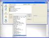
When you turn on the ScanTo3D add-in there is a new toolbar available that gives you three buttons. The first button can be used to initiate a NextEngine scan (if you have one). The second and third buttons are the Mesh Preparation Wizard and Surface Wizard. The same three options are also  available under the Tools menu. When you go to open a file, two new options are available under the “Files of Type” pull-down. You can open Point Cloud data files and Mesh Files in various formats (See figure to the left). Point Cloud data files are often the result of data collection using a CMM (Coordinate Measurement Machine) or Digitizing Arm. If you have files in this format, ScanTo3D will import the data and give you the tools to create a mesh using the points in free space. Mesh Files are tessellated files (made up of polygons or triangles) that are often generated from 3D Digitizing Scanners, CAD data (usually for rapid prototyping), or data from 3D graphics and animation packages.
Let’s start with bringing in some Point Cloud data. If you wish to open a Point Cloud data file and run the Mesh Preparation Wizard you must do so from the Open dialog box with the “Files of type” set to “Point Cloud Files”. (The Point Cloud data could actually be in .IGES or .VDA format. If they are not opened with the “Point Cloud” file type set, the data will import much like it would in previous versions and the ScanTo3D functions will not work. With the file type set correctly, ScanTo3D will create a “PointCloud1” feature in the FeatureManager Design Tree. When importing Point Cloud Data, the first option available will be the Mesh Preparation Wizard. I know how some of you probably feel about wizards in general, but I must say that this one is put together better than most I have seen. Not every step in the wizard requires input from the user. If a particular step doesn’t apply to you, most of the time you can move on to the next step in a pretty painless manner.
The first option in the wizard is a verification of which Point Cloud feature you would like to use for mesh generation. The interface also displays the number of points present upon import. In the next dialog, ScanTo3D will allow you to orient all of the points as a group to a different position or orientation using either automatic, reference based, or numeric inputs. The next option you have is a slider bar that allows you to remove “noise points” based on the distance between points.
 A common problem that can occur with 3D manual digitizers can be “ghost” points or points that were recorded but are obviously not in the correct location to define the part’s shape. Points like this can really affect the shape and validity of the mesh. With the next step in the wizard, Scanto3D gives you four different selection methods to remove extraneous data points. Data can be selected using box selection, polygon selection, lasso selection, or brush selection (Brush selection is primarily used if sub-meshes exist. We will look at that in Part II of this review later). The next step brings you to the simplification options. By using a slider bar or percentage adjustment, you can reduce the amount of points present in the mesh. An up-to-date preview of the points is shown in the graphics area. The PropertyManager also does a good job showing the would-be reduction in data points if the step is completed. After completing this step, the initial Mesh is generated, but you are still in the wizard with several options to go.
 The initial mesh preview is now shown and the Smoothing options appear. A slider bar is available to adjust the global smoothness of the entire mesh or localized areas can be defined for smoothing using the three selection tools
  available. Next up the wizard brings you to the Fill Holes dialog. ScanTo3D automatically detects and selects all holes in the mesh geometry. You can de- select any open patches that you would like to remain in
  the mesh. After completing this step we reach the end of the Mesh Preparation Wizard. If you wish to use the ScanTo3D surface creation tools, there is an option to launch the Surface Wizard. We will cover that feature in Part II of this review.
The Mesh Data by itself can be very helpful reference information if the approach is taken to use it as a guide to create a complete feature based model of the scanned object. The sketches and features are built virtually on top of the mesh data so that the constructed shape can be constantly checked against the mesh. The vertices of a mesh created or imported using ScanTo3D can be snapped to by any sketch geometry as you build and create your features around it.
A few months back while SolidWorks 2007 was still in Beta, I had a project come along that really benefited from some of the functionality offered in ScanTo3D. Throughout this review you have  seen screen shots using the actual CMM data that was collected for this project. I
 have added a few additional screen shots that show the completed SolidWorks feature based model and how the finished geometry compares to the mesh geometry created from the point cloud. Incidentally, this model used other new SolidWorks 2007 features which included Boundary Surface and Curvature Continuous Surface Fills.
Part 2 of this review will look at the Surface Wizard along with some additional options that can affect the Mesh as well. Stay tuned for Part 2…….