In Part 1 of my review of ScanTo3D, we covered importing point cloud data and converting that data into mesh data using the Mesh Preparation Wizard. In this second installment we will take a look at some surface creation functionality that is also part of the ScanTo3D product.
Once you have existing mesh data, you are able to run the Surface Wizard. You can get mesh data into ScanTo3D by either running the Mesh Preparation Wizard on point clouds as we saw in Part 1, or by importing mesh data directly in various tessellated formats (which includes STL, VRML, OBJ, and 3D Studio Max formats). The example you will see in this article will be an imported .STL file
 As you can see in the figure to the left, the STL file comes in as a mesh feature when you set the Files of type in the Open dialog box to “Mesh Files”. If you open the STL file using the “STL” type setting, it will not result in a mesh feature as this is the “legacy” STL import option that has been available for the past few releases. Anyone who has tried this import option knows that anything other than the “graphics body” option results in bloated file sizes and slow overall performance when working with the data. On top of that, there really isn’t much you can do with it except modeling on top of it. With ScanTo3D’s mesh import, the overhead problem has been non-existent in all of my test cases thus far.
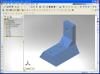
 As you can see, I have picked a fairly simple part for this operation. This will result in less trimming and secondary model operations versus a more complex part that might have fillets or complex surfaces. Upon starting the Surface Wizard, your first dialog will ask you to select a single mesh for the operation. ScanTo3D brings in most STL & VRML objects (that I have tested) as a single mesh feature (even if there are multiple bodies that do not touch). This is handy in that you can potentially run a single Surface Wizard operation on many objects without having to repeat the wizard for each mesh. There are no “limits” as to how many times you run any wizard in ScanTo3D. If you have multiple meshes or point clouds, you can run the wizards for each object. Once you select the mesh, the PropertyManager tells you how many faces that mesh contains.
 After selecting the mesh, we move to the next step which gives you choices on how to create your Solid/Surface body. There are two options presented: Automatic and Guided Creation. The Automatic Creation will basically do all the work for you. However, the results can differ based on the shape of the mesh. This option seems to be better with complex shapes that have tangent or curvature continuous
  surfaces. It creates and knits a continuous “web” of surfaces that overlay the mesh. As you can see in the example to the right, if you run the Automatic Creation option on our prismatic part, we don’t get the result we are looking for. The Guided Creation allows the user to interact in the creation of the surfaces that are extracted from the mesh data.
 The next dialog shows an option to designate a split plane which allows you to extract surfaces for only half the model in the event that it is symmetric. Although our part is symmetric, I bypassed the option and extracted faces of the entire model.
The next step brings us to the Face Identification stage. ScanTo3D analyzes the model and recommends how the faces should be separated for surface extraction. Like any automated tool, it cannot read your mind and will not always separate the faces in the exact way you want it to, but it  does a great job of getting the process started. The sensitivity bar allows you to adjust the degree of which the faces are separated. Face classifications are displayed in the graphics area by the use of colors. Each face or set of faces are assigned unique colors to indicate the manner of which the mesh will be divided. After close examination of the default face classifications (see figure to the left), the
 only modifications that are needed are the separation of the faces on the each side of the part and some of the centerline faces. By default they are shown in the same color as compared to other adjacent faces. If they remain that way, ScanTo3D will attempt to “fit” a single surface to both faces. Below the sensitivity bar are some “Manual Painting” tools that allow the user to color faces as they see fit. Using these tools, you can quickly re-color faces to get the desired classification.
 The next dialog is the Surface Extraction step. The number of regions defined
 ![]() with colors in the previous step is displayed and a quick fly-out display of the FeatureManager Design Tree shows that the mesh has been divided into sub-meshes based on the regions. To have ScanTo3D automatically extract all faces to surface bodies at once, the
with colors in the previous step is displayed and a quick fly-out display of the FeatureManager Design Tree shows that the mesh has been divided into sub-meshes based on the regions. To have ScanTo3D automatically extract all faces to surface bodies at once, the  “Extract All Faces” button can be selected. If you want to extract each surface individually, you can click on each face/region and choose from the surface type you wish to fit to that area. The types available are shown in the figure to the right. In this case, all of the regions are either planar or cylindrical, so the “Extract All Faces” option works well.
 The process of extracting the faces does not simply copy the exact size of the existing face. The extracted surface is automatically extended on all boundaries to make trimming of the multiple surfaces much easier. As you can see in the figure
 to the left, ScanTo3D generates separate surface bodies for each assigned region (color). The wizard informs us that the surface creation is complete. The mesh was divided into sub-meshes as we mentioned earlier, but still remain in the feature tree. They are automatically hidden by ScanTo3D as the surfaces are created. With a few Trim operations, the model is complete and converted to a solid body. (See figure to the right)
ScanTo3D is currently only offered as part of the SolidWorks Office Premium bundle which has created a few comments from the SolidWorks user community. Some users have voiced their opinion that this add-in should be made available for separate purchase if someone does not want the additional add-ins offered with Premium (COSMOSWorks Designer, SolidWorks Routing, & Design Checker). The cost to upgrade from SolidWorks Office Professional to SolidWorks Office Premium is $3,500. There are other higher end packages out there that do what ScanTo3D does and more that cost upwards of $10,000. The options available in the ScanTo3D package are very impressive, especially for a first release. There is no doubt that this adds great value to the Premium Upgrade itself. Having the ability to do static stress analysis, pipe-tubing-electrical routing, automatic drawing checks, & and all the options presented in ScanTo3D is quite a bargain at $3,500. Personally, I have made good use of my upgrade as I have used COSMOS and Routing quite a bit in addition to ScanTo3D. On the other end of the spectrum, I can understand why someone who may work exclusively on reverse engineering models would want to buy it as a separate item. My recommendation to those folks would be to let your VAR know how you feel. If enough people ask….things can sometimes change.
Hopefully this review will help you better understand the features offered in ScanTo3D. SolidWorks has quite a bit of information on the ScanTo3D page of their website. There is a video presentation that demonstrates most of the ScanTo3D processes that you definitely want to check out.
Stay tuned for more SolidWorks 2007 feature reviews!!